Overcoming Code Challenges
Calculating Roof Area for Roof Drain Sizing
By Anjian Lu, CPDTHE DILEMMA
Plumbing engineers often work on projects that, because of location, are governed by different plumbing codes. Variations among the codes sometimes cause confusion and present challenges either within the design group or between the designer and the plan reviewer or inspector. The roof area calculation for sizing roof drains is an example of how differences among the codes can challenge the designer.
We all agree that vertical walls contribute flow to roof drains because they collect rainwater when wind driven rain hits and runs down the wall. How do vertical walls affect the sizing of roof drains? The codes differ in their answers to this question.
CODE SEARCH
A search of the national codes found the following references to calculation of roof area for sizing roof drains.
National Standard Plumbing Code (NSPC)
13.1.10.3 Vertical Walls: Where vertical walls drain onto roofs, an allowance based on 50 percent of the maximum projected wall area shall be added to the roof area onto which each wall drains.
International Plumbing Code (IPC)
1106.4 Vertical Walls: In sizing roof drains and storm drainage piping, one-half of the area of any vertical wall that diverts rainwater to the roof shall be added to the projected roof area for inclusion in calculating the required size of vertical conductors, leaders, and horizontal storm drainage piping.
Uniform Plumbing Code (UPC)
1106.4 Side Walls Draining onto a Roof: Where vertical walls project above a roof so as to permit storm water to drain to the roof area below, the adjacent roof area may be computed from Table 11-1 as follows:
- For one wall, add 50 percent of the wall area to the roof area figures.
- For two adjacent walls, add 35 percent of the total wall areas.
- For two opposite walls of the same height, add no additional area.
As you can see, NSPC requires 50 percent of the maximum projected wall area to be added to roof area calculation.However, the designer has to project the wall area in different directions and take the maximum area.
IPC tells you to add one-half of the area of any wall that diverts rainwater to the roof, to the roof area. Here, any means all.
UPC’s guideline is much more clear and executable. I’ll explain why UPC set the table this way.
GEOMETRY IN ROOF AREA CALCULATIONS
First, rainfall density is measured by a rain gauge (See Figure 2), which consists of three parts: a cylindrical overflow tube, a funnel on top, and a measuring tube underneath the funnel. The funnel diverts water into the measuring tube, which is one-tenth of the area of the funnel top for more accurate reading. The overflow tube stores water when the measuring tube is full and overflows. Now, imagine that the funnel top is a part of the roof.
Let’s look at a real roof as an example.
Figure 1 shows a simple roof with projected high roofs. The four roof drains in this roof are A, B, C, and D. Roof drains A and C are the same and have two perpendicular walls. Roof drain D has one vertical wall, and roof drain B has two opposite walls.
Suppose rain hits the wall in angle α. We then can draw a triangle abd. Its three sides are ad, dc and ca. We express their length with an upper score in the functions to follow.
Let’s look at the horizontal roof draining to roof drain C first. If the wall length is LC and the area is ACH, then
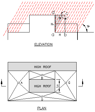 |
| Figure 1 Example roof and roof drains |

The flow, QCH, caught by area,
 shall equal that caught by area,
 , or:
, or:
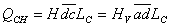


H = rain density
Hv = rain density on the vertical wall
From above we know:
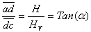
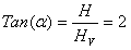
Since the plumbing code requires use 50% of the wall area, i.e., Hv = (1/2)H, then
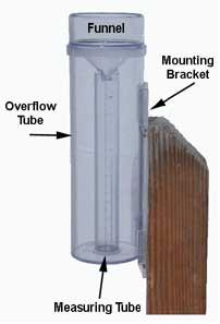 |
| Figure 2 Rain gauge Source: CoCoRaHS |
Now, what about the wall north of roof drain C? If there is no wall on the west, the answer is as simple as taking one-half of the area of the wall since wind direction is unpredictable.
UPC suggests using 35 percent of the total area of both walls. In most situations, this is reasonable because rain hits both walls in 45o angle, i.e., Hv = (1/2)H x sin(45) = 0.5x0.707 = 0.3536 or 35%. However, if one of the walls is much larger than the other, the drain may be undersized. On the other hand, if you take the 50 percent of the total area, the drain may be oversized. For this reason, the NSPC’s guideline, which requires using 50 percent of the maximum projected area, may be the best solution.
As for areas with opposite walls, such as the area for roof drain B, UPC’s guideline No. 3 of adding no additional area to the calculation is adequate. However, if the two walls are not of the same size, the difference between the two areas should be added. As you can see from Figure 2, the funnel of the rain gauge can be considered as a round 360-degree wall in the periphery of the building roof. The rainwater recorders do not take the roof geometry into account, so we, as engineers, should.
SUGGESTIONS
Based on the analysis above, I offer the following suggestions for your consideration.
For Single Roof DrainsFor single vertical walls affecting the collection area of a roof drain, add 50 percent of the side area to the total for calculating the flow rate.
For single curved vertical walls, use 50 percent of the maximum projected area.
For multiple walls, use 50 percent of the maximum projected area of all walls.
For drain areas between two opposite walls, add no additional area. If the area of each wall is not the same, add 50 percent of the difference between the two areas.
For Horizontal Pipes or Leaders Receiving Two or More Roof DrainsTake only 50 percent of one maximum total projected side area of the walls in one direction.
For the Whole Roof of a BuildingDo not add any side wall area except when the projected wall area is falling off the roof boundary. To decide this, use the architectural elevation drawing to draw a 63-degree line starting from the top of the highest wall (the hypotenuse of a right triangle with bottom length of 1 and height of 2). Add 100 percent of the horizontal area falling off the roof boundary to the total horizontal roof area for sizing the building rainwater drain.
For Riser DiagramsWe may not have to put the exact arithmetic sum of the branches to a main or submain. This is because when a wall may affect one part of the piping, it may not affect the downstream part as mentioned above.
CONCLUSIONS
While properly sizing the roof drainage system is very important for structural safety, calculating roof area can not be overlooked. A uniform method in all the plumbing codes nationwide is a request from the plumbing engineers like me.
With 3D MEP AutoCad or Revit increasing in popularity, it should be not difficult to determine the correct projected area for sizing the rainwater system—the roof drains, leaders, gutters, downspouts, and horizontal piping.
Anjian Lu is a plumbing engineer with Affiliated Engineers Inc. in Rockville, Maryland. For more information or to comment on this article, e-mail articles@psdmagazine.org.
(Source: Plumbing System & Design, June 2009)